How does the computer discover what to load when turned on?
In this article, we explore the technical process of computer initialization, detailing the loading of the Master Boot Record (MBR), the disk sector structure, and the implementation of an Assembly bootloader focusing on boot signature validation.
Bootloader Loading
Upon powering on, the hardware executes the Power-On Self Test (POST). Following component validation, the BIOS searches for bootable storage devices. The first physical sector (the initial 512 bytes, known as the boot sector or MBR) is loaded into RAM. The BIOS validates the integrity of this sector by looking for the “magic signature” 0xAA55 in its last two bytes; if present, execution is transferred to this address and the boot process continues.
⚠️ Technical Note: Introduced in 1983, the MBR (Master Boot Record) was the dominant standard for decades. Currently, modern systems use the GPT (GUID Partition Table), which overcomes MBR’s partitioning and disk size limitations. For educational purposes, we will use the MBR model in this article.
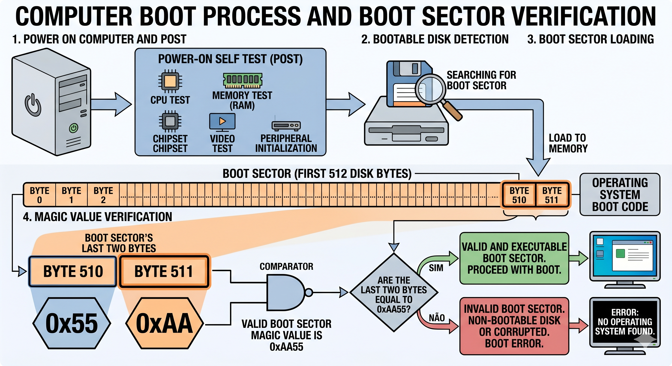
Disk Geometry and Sectors
To understand data organization, consider the structure of a conventional Hard Disk Drive (HDD). The disk is organized hierarchically into sectors, tracks, and heads.
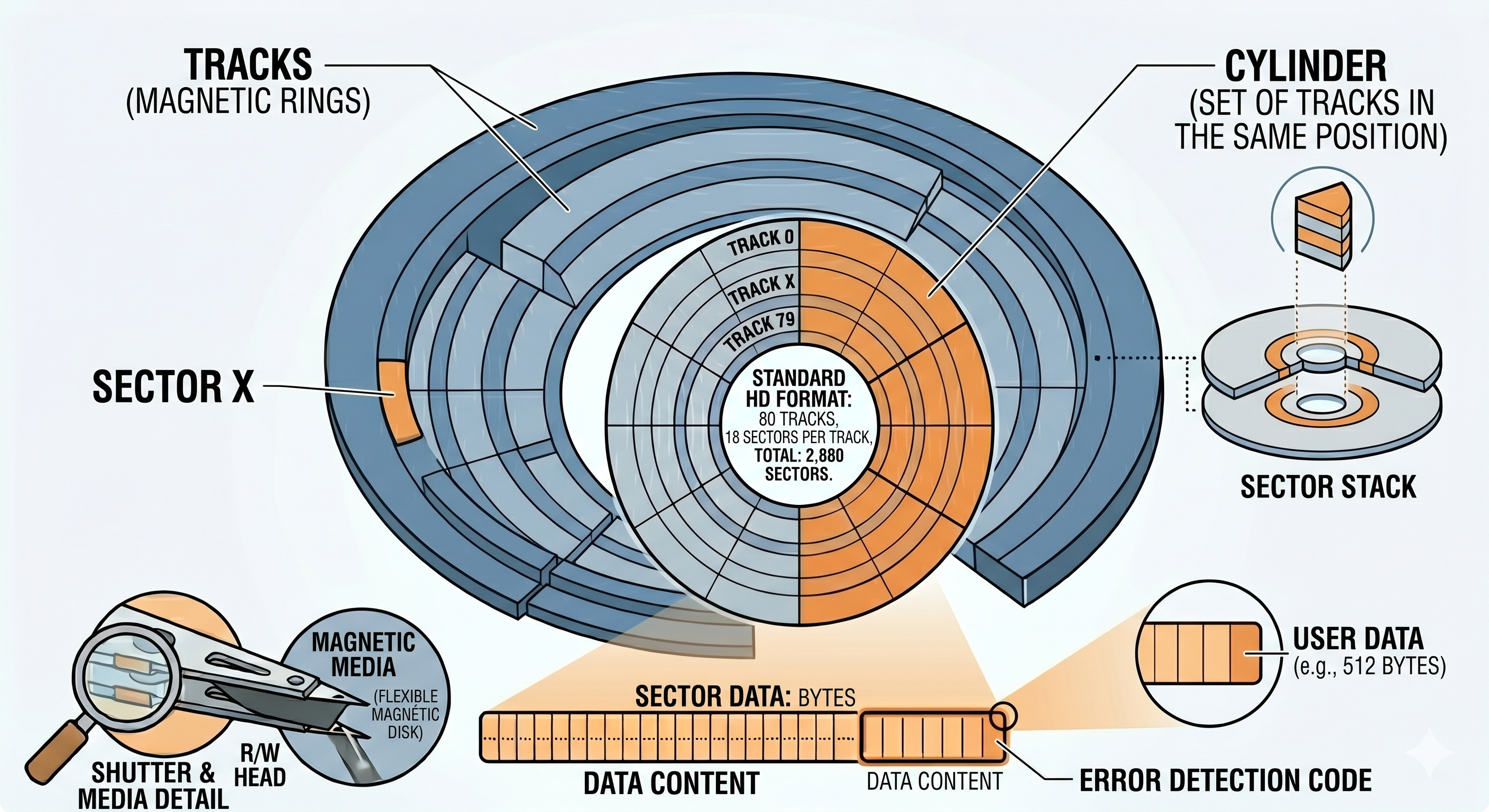
The MBR (Master Boot Record) is located in the first physical sector of the disk. This sector has exactly 512 bytes of capacity, the space where the first stage (Stage 1) of the operating system bootloader is defined.
Boot Sector Implementation
Bootloader development is typically done in Assembly, ensuring direct control over hardware and memory mapping. Below is an example implementation:
1
2
3
4
5
6
7
8
9
10
11
12
13
14
15
16
17
18
19
20
21
22
23
24
25
26
27
28
29
30
31
32
33
34
35
36
37
38
39
40
41
42
43
44
45
46
47
48
49
50
# ***********************************************************
# Example Boot Sector
# ***********************************************************

.code16
.intel_syntax noprefix
.text
.org 0x0

LOAD_SEGMENT = 0x1000                     # The 2nd stage loader will be loaded at segment 1000h
FAT_SEGMENT  = 0x0ee0                     # The boot disk FAT will be loaded at segment 0x0ee0
                                          # (9*512 bytes below the 2nd stage loader)

.global main

main:
    jmp short start                       # Jump to the start of the code
    nop                                   # Alignment (nop) for the boot sector header

.include "bootsector.s"
.include "macros.s"

start:
  mInitSegments                           # Initialize memory segments
  mResetDiskSystem                        # Reset the disk subsystem
  mWriteString loadmsg                    # Display loading message
  mFindFile filename, LOAD_SEGMENT        # Locate the 2nd stage file in the root directory
  mReadFAT FAT_SEGMENT                    # Load the FAT table into memory
  mReadFile LOAD_SEGMENT, FAT_SEGMENT     # Transfer the 2nd stage into RAM
  mStartSecondStage                       # Transfer execution flow to the 2nd stage

# Boot process failure handling routine
bootFailure:
  mWriteString diskerror                  # Display disk error message
  mReboot                                 # Request system reboot

.include "functions.s"

# Data and constants definition
filename:    .asciz "2NDSTAGEBIN"
rebootmsg:   .asciz "Press any key to reboot.\r\n"
diskerror:   .asciz "Disk error. "
loadmsg:     .asciz "Loading DevOS...\r\n"

root_strt:   .byte 0,0      # Root directory offset
root_scts:   .byte 0,0      # Number of sectors in the root directory
file_strt:   .byte 0,0      # Bootloader offset on the disk

.fill (510-(.-main)), 1, 0  # Padding with zeros up to byte 510
BootMagic:  .int 0xAA55     # Magic signature for BIOS recognition
Technical Analysis and Boot Signature
The implementation uses specific directives to ensure compliance with the MBR standard. The critical point lies in padding the sector to reach exactly 512 bytes (lines 49 and 50).
Since the volume of instructions and data may vary, it is necessary to dynamically calculate the required padding. The expression used is:
(510 - (.-main))
Expression components:
.(dot): Represents the current location counter.main: The address of the initial entry point.(.-main): Calculates the total byte offset generated so far.510 - (.-main): Determines how many bytes remain to reach the 510-byte mark.
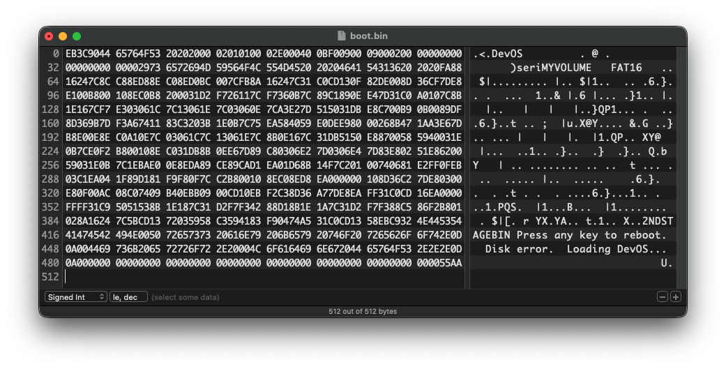
The final two bytes (511 and 512) are reserved for the 0xAA55 signature. Without this signature, the BIOS will not recognize the device as bootable.
Binary Generation and Loading into RAM
After assembling the source code, a binary file is generated. When the computer identifies a boot device, the BIOS reads the first sector (512 bytes), copies its content to the physical memory address 0x7C00, and begins executing instructions from that address.
Next Steps and Conclusion
Operating system initialization is a multi-stage process. The analyzed code represents Stage 1, whose primary function is to locate and load the subsequent stage into RAM, as demonstrated by the logic starting at line 23.
In future articles, we will detail the later phases, including the transition to Protected Mode and Kernel loading.